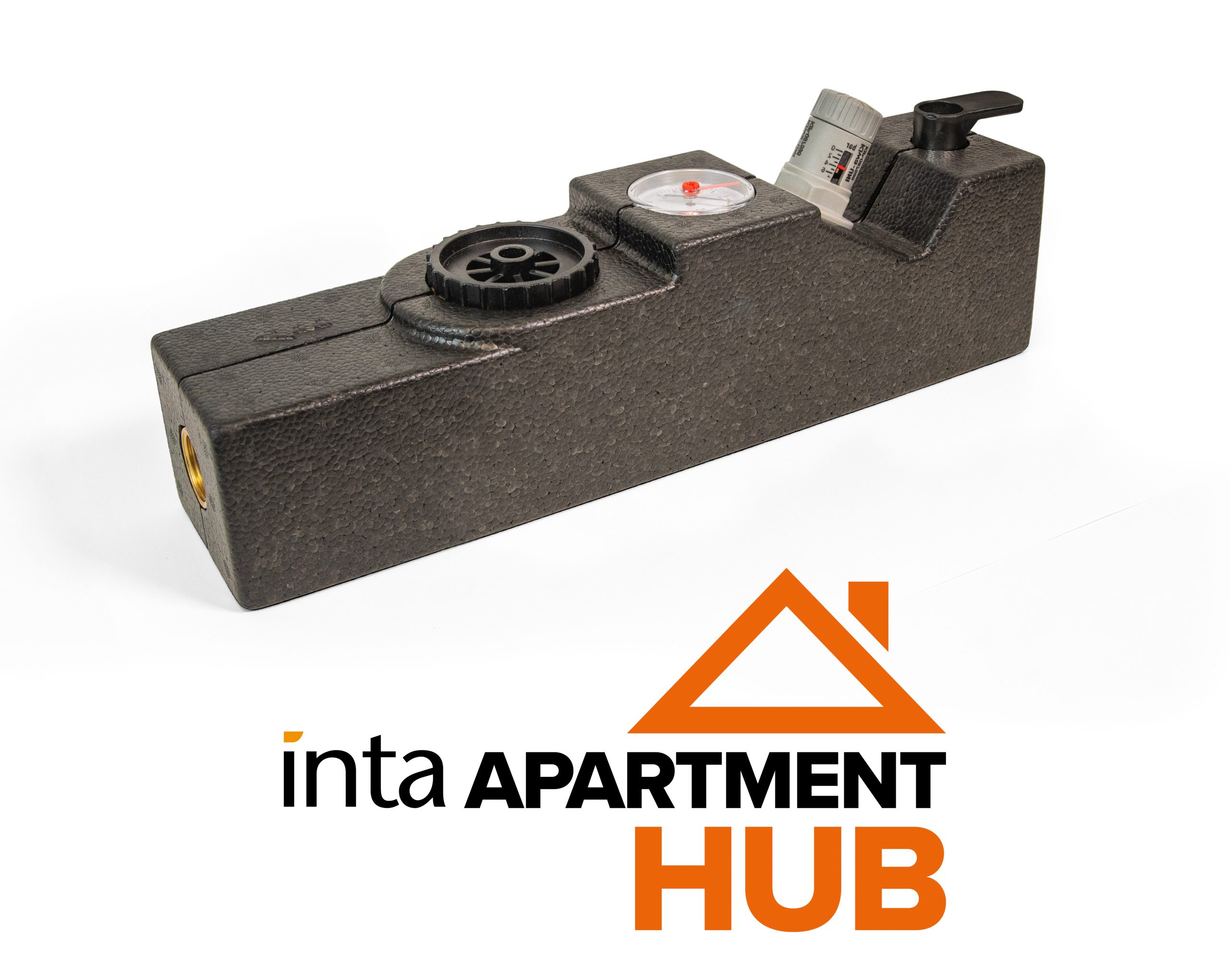
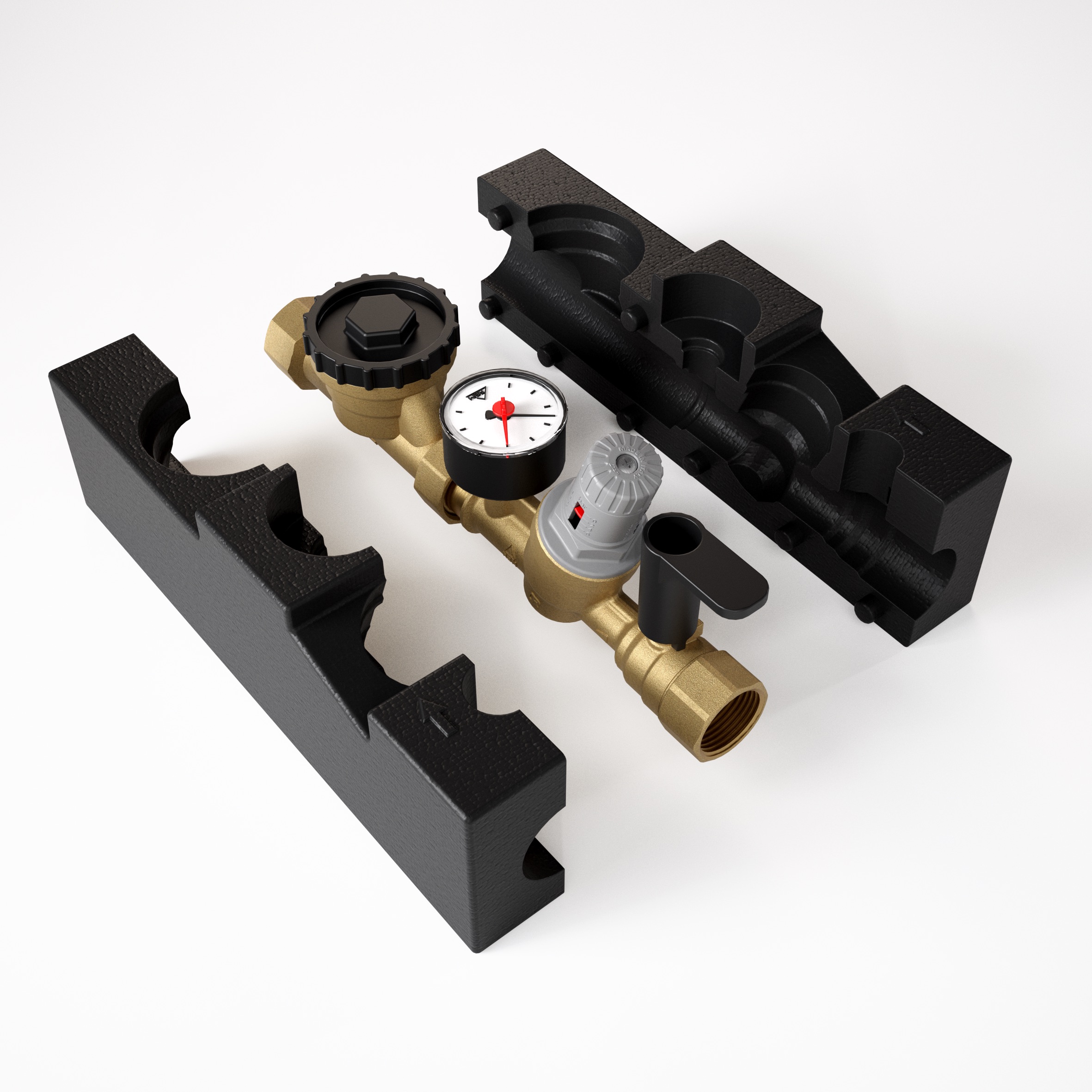
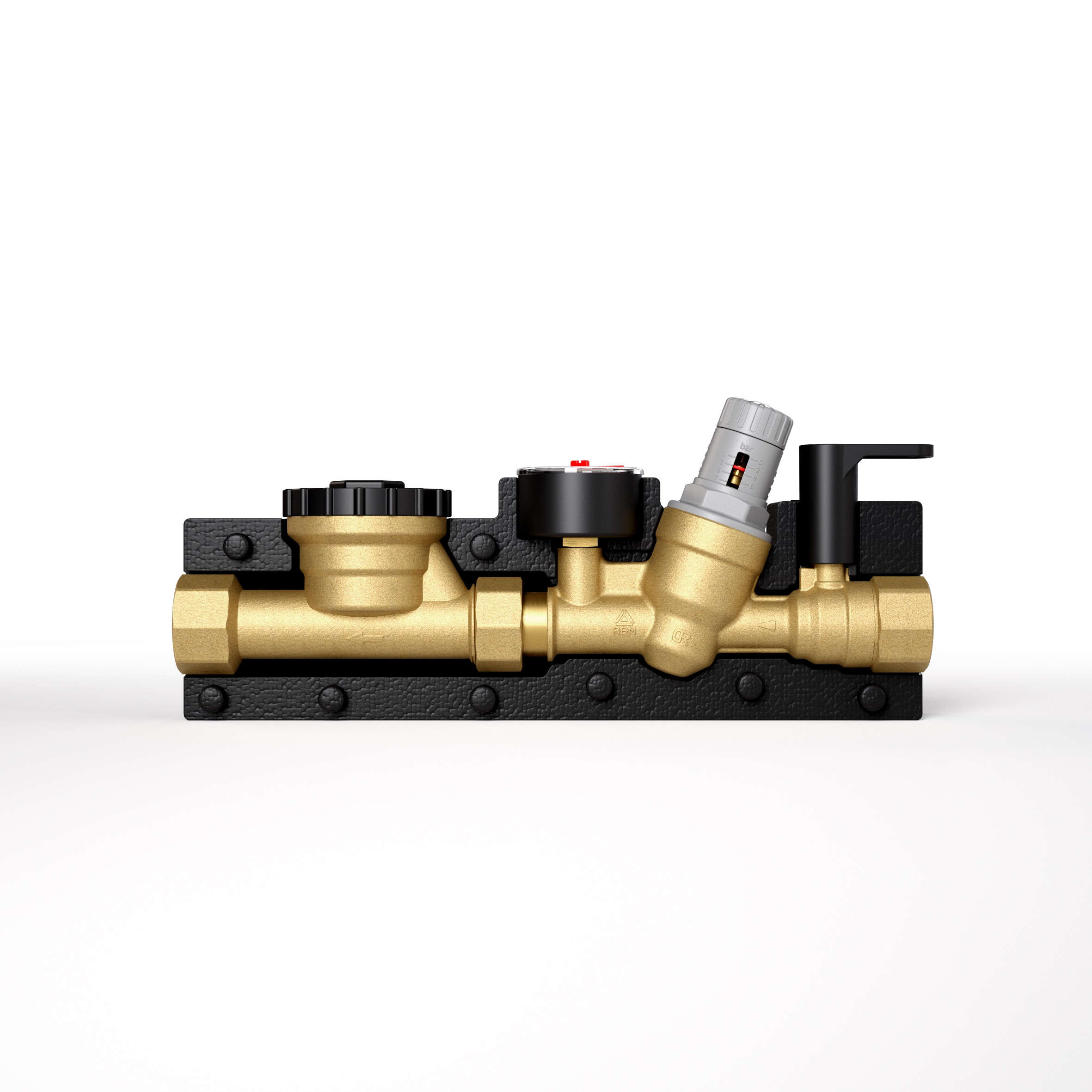

The Inta Water Meter Assembly is a combination valve providing a stop valve, pressure reducing valve, pressure gauge, class D water meter carrier and double check valve in one convenient and easy to fit unit.
The Inta Water Meter Assembly valve is provided complete with a whole assembly moulded insulation cover.
| Max Inlet Pressure (static) | 16 bar |
| Min Inlet Pressure (dynamic) | TBA |
| max Inlet Temperature | 65°C |
| Pressure Adjustment Range | 1-6 Bar |
| Installation | Vertical or Horizontal |

Class D water meter carrier
Combines an isolation valve, double check valve, pressure reducing valve, and water meter all-in-one unit.
Pressure reducing valve is pre-set to 4 bar, but can be manually adjusted to suit site conditions.
Supplied with a whole assembly insulation jacket as standard.
Double check valve to eliminate the change of backflow.
Stop valve included to allow isolation from the rest of the system, ideal for multi-dwelling properties.
In order to prevent cavitation, which can cause excessive noise, vibration and damage to the valve and downstream pipe, in certain pressure situations with high inlet pressures and low outlet pressures (high pressure loss) then a number of pressure reducing valves may be required.
The cavitation diagram show three areas of operation depending upon the upstream and downstream (outlet) pressures.
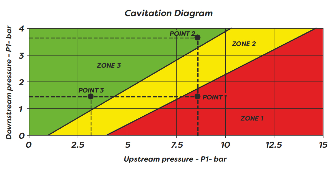
In order to avoid cavitation occuring the ratio between the maximum upstream pressure and the outlet pressure should not exceed a value of 2.5.
*NOTE: The cavitation diagram has the sole purpose of supplying the technician with a quick reference for the system conditions to determine if cavitation will be present and the likely level.
If the pressure reducing valve is used under the following conditions;
On the Cavitation Diagram these pressures correspond to POINT 1 in ZONE 1.
Ratio Pm/Pv = 8.5/1.5 = 5.67.
Use 2x pressure reducing valves in series, if a second pressure reducing valve is required we recommend that this is installed upstream of the flow valve at a distance of at least 30cm.
First valve using the following conditions;
Pressure ration 8.5/3.5 = 2.42 < 2.5
On the Cavitation Diagram these pressures correspond to POINT 2 in ZONE 3.
Second valve using the folllowing conditions;
Pressure ration 3.5/1.5 = 2.33 < 2.5
On the Cavitation Diagram these pressures correspond to POINT 3 in ZONE 3.
*NOTE: The outlet pressure of the pressure reducing valve MUST NEVER be higher than the maximum pressure of components and outlets (tap and showers) downstream of the valve.


