Preferred Heat Meters shall be battery powered) with a wired Mbus output and shall;
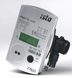
The Ista Ultego III smart is a compact heat meter for physically accurate recording of energy consumption. The device comprises of a flow sensor, two fixed connected temperature sensors and a calculator that calculates energy consumption using the volume and temperature difference.
The meter is very easy to install and read. With its outstanding properties, such as high metering precision, freedom from maintenance and long service life, the Ultego III smart contributes to minimising annual operating costs.
Volume recording works in accordance with the wear-free ultrasound metering principle with no mechanical moving parts.
The water volume is measured in the meter pipe via ultrasonic pulses emitted in and against the direction of flow. The time between transmitter and receiver is reduced downstream and extended upstream accordingly. The water volume is then calculated from these metered values.
M-Bus (Meter Bus) is a European standard for the remote reading of heat consumption by heat interface units and was developed to fill the need for the networking and remote reading of utility meters. The M-Bus interface is made for communication on two wires as the most cost effective solution, but a wireless version is also available.
The principle is based on a master – slave procedure, the master is the data logger, and the slave being the heat meter.
When interrogated, the meters deliver the data they have collected to the common master. Another method is to transmit meter readings vis GPRS or GSM. The data is then stored until required for billing. M-Bus cable is protected against reverse polarity, the wires are interchangeable.
For M-Bus wiring use two core no smaller than 2.5mm cable, and wire the heat meters as directly as possible avoiding excess cable. Label all the wiring and distribution and junction connection points. The maximum length of cable can be from 1000m to 4000m, and is dependant on the number of meters and the character of the cable, the lower the resistance the better. High resistance caused by using for example smaller cables may risk transmission errors.
Specification for M-Bus communication between the heat meter and ista SmartPay Control Unit:
Up to 128 heat meters can be connected to a M-Bus network, (up to 250 when broadband connection used) and data loggers come in different sizes, so select the appropriate option. The more meters in connection, then the shorter the maximum cable length, and for 250 meters to one data logger then the total maximum length of cable is 1000m.
Essentially the MBus data loggers come in the following configurations:
Should you require technical support for the Hiper HIU unit during this period, please contact one of our service providers in your area, who will be happy to help.
Please note, you will be required to provide the following information:

Cover: Scotland
Phone: 0141 4141411
Email: scotland@thermalcare.co.uk
Please call the office number and this will put you thought to out of hours.
Cover: London Areas
Phone: +44 (0) 207 247 9304
Email: info@sandhurstplumbing.co.uk
Address: 18 Blount Street, London, E14 7BZ
Cover: England
Address: Building Centre, 26 Store Street, London, WC1E 7BT
Phone: 077 0449 7243
Email: aruna@heatweb.co.uk
Cover: Midlands, North & North Wales
Address: Unit 3 Chemical Lane Longbridge Hayes Ind Estate, Stoke-on-Trent , ST6 4BP
Phone: 01782 630656
Email: ange.holland@HMM.co.uk
Cover: London Areas
Phone: 07725920241
Email: aaron@hiumechservices.com
Address: 53A lansdowne lane , London, SE7 8TN